Thread Geometry
Review pitch, depth, start, shrinkage and assembly engagement.
Injection Mold Type
Unscrewing molds release molded threads through a controlled rotating core or related mechanism before ejection, protecting functional thread geometry that cannot be stripped from the tool.
What Makes This Tooling Different
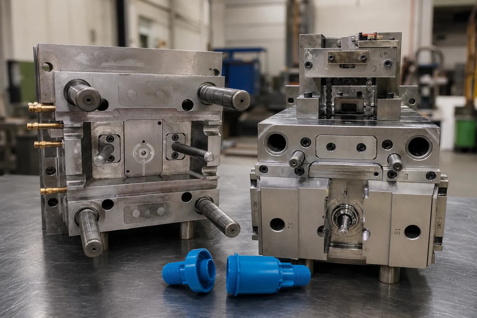
The tool must synchronize thread rotation, core travel and part ejection. Thread geometry, drive concept, wear and maintenance are therefore central to the mold—not secondary details.
This tooling route should be selected from the part, material, production demand and receiving-machine requirements—not from a category name alone.
Selection Criteria
Internal or external threads that cannot release by deformation
Functional threaded interfaces requiring controlled form
Parts where a collapsible core or slide is not the practical release route
Type-Specific Engineering
Review pitch, depth, start, shrinkage and assembly engagement.
Select motor, gear, rack or other verified mechanism around stroke and receiving-machine needs.
Coordinate unscrewing completion before ejection and protect the return sequence.
Plan service access and wear components around rotating cores and gears.
Critical Tooling Topic
A stable sequence protects both the molded thread and the mechanism during every cycle.
Unscrewing stroke and turns
Core rotation before ejection
Part restraint during release
Return confirmation and maintenance access
Real Engineering Evidence
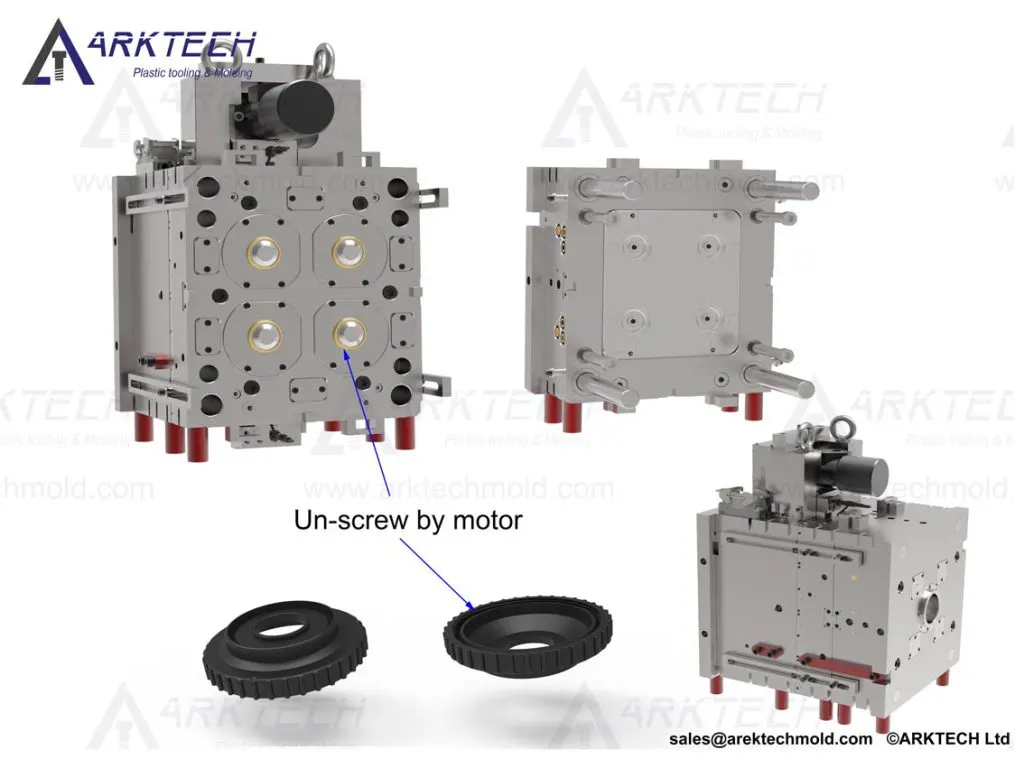
The project image shows a real motor-driven unscrewing tool beside internally threaded molded components.
Trial & Validation
Inspect thread form for short fill, damage and incomplete release.
Use the agreed mating part or gauge when thread performance is critical.
Check drag and witness marks after unscrewing and ejection.
Repeat the mechanism cycle and review timing, noise and return position.
Related Capabilities
Project Inputs
FAQ
It is considered when molded threads cannot be released reliably by normal draft, deformation, a slide or another simpler release method.
The verified drive can use a motor, gear, rack, hydraulic or other mechanism depending on thread geometry, travel, cycle and receiving-machine conditions.
Validation can include visual thread review, dimensional inspection, mating-part assembly or an agreed gauge, plus repeated mechanism cycling.
Project-specific spares may include wear-sensitive cores, gears, bearings, seals or related mechanism components identified during design and trial.
Start Your Tooling Review
Send your CAD data, material, volume and receiving-machine requirements for DFM review and tooling quotation.