Insert Positioning
Locate the insert from stable features and define orientation clearly.
Injection Mold Type
Insert molding tools locate and retain prepared metal or other components while plastic is molded around them to create a controlled integrated part.
What Makes This Tooling Different
Insert position must remain stable against injection pressure while shutoffs control flash and protect the inserted component. Loading access, poka-yoke and mold protection need to be designed around the real insert condition.
This tooling route should be selected from the part, material, production demand and receiving-machine requirements—not from a category name alone.
Selection Criteria
Metal terminals, bushings or threaded inserts integrated into plastic
Components requiring repeatable insert orientation
Programs seeking to reduce a later assembly operation
Type-Specific Engineering
Locate the insert from stable features and define orientation clearly.
Prevent movement, lift or deformation under injection pressure.
Develop durable shutoffs around insert interfaces without damaging the insert.
Review manual or verified automated loading, error prevention and missing-insert protection.
Critical Tooling Topic
The insert, plastic flow and tooling shutoff should be evaluated as one functional interface.
Insert drawing and incoming tolerance
Location and anti-rotation features
Plastic coverage and knit-line risk
Pull-out, torque or electrical function where required
Real Engineering Evidence
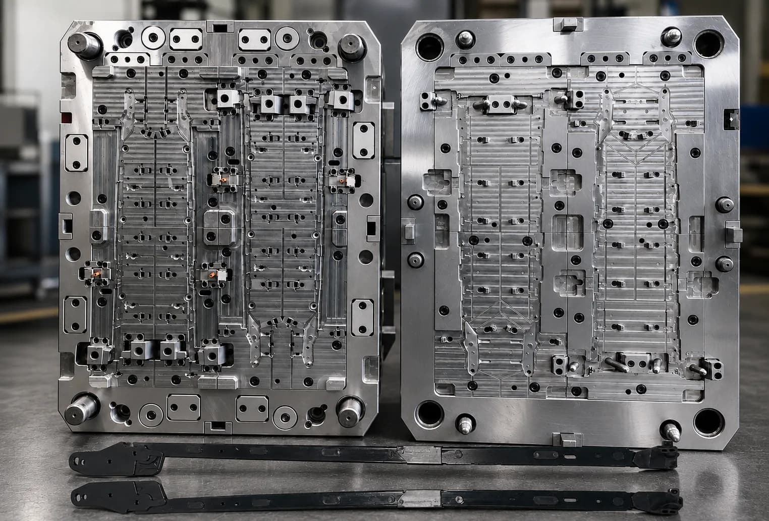
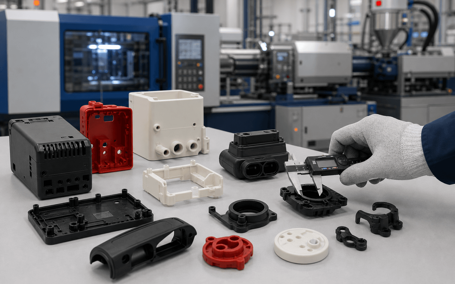
The hero is an approved real insert-molding tool image. The supporting production visual is used only to show molded-component manufacturing context.
Trial & Validation
Inspect location, depth and orientation against the drawing.
Perform agreed pull, torque or functional checks where the interface requires them.
Review sealing areas and confirm the insert is not bent, marked or contaminated.
Check thread, electrical, sealing or assembly performance as applicable.
Related Capabilities
Project Inputs
FAQ
Common examples include threaded inserts, bushings, terminals, pins and prepared metal components. Suitability depends on geometry, tolerance, surface condition and functional requirements.
The mold uses locating and retention features designed around the insert, plastic pressure and loading method. Trial samples confirm whether the position remains stable.
Manual loading can be appropriate for some volumes and insert types. Automated loading should only be specified when the project, equipment and insert presentation support it.
Checks can include insert position, flash, molded dimensions, pull or torque performance, electrical continuity or assembly fit according to the part function.
Start Your Tooling Review
Send your CAD data, material, volume and receiving-machine requirements for DFM review and tooling quotation.