
Multi-Cavity Mold
- Multiple identical parts
- Focus on cavity-to-cavity consistency
- Suitable for repeat production
- Balanced filling and cooling are critical
Production Tooling
Multi-cavity tooling produces multiple identical parts in each molding cycle and requires careful cavity layout, filling balance, cooling and cavity-to-cavity validation.
Balanced Filling · Cooling Strategy · Cavity Identification · Trial Validation
Tooling Selection
Both approaches can produce more than one part per cycle, but they solve different production requirements.
Production Scale-Up
Depending on project stage and production requirements, tooling may move from lower-cavity validation into multi-cavity production tooling. A preliminary single-cavity tool is not required for every program.
Product / Design Validation
Production Volume Review
Cavity Count Evaluation
Multi-Cavity Mold Design
Mold Manufacturing
Trial & Cavity Validation
Production
Tooling to Production
Validated multi-cavity molds can continue into plastic injection production at Arktech when customers prefer tooling and molding under one workflow, supported by molding equipment from 25–550T.
Cavity Planning
Cavity count is an engineering and production decision. Arktech does not apply a fixed number before reviewing the part, mold and receiving-machine conditions.
Expected Production Volume
Part Size & Geometry
Material
Mold Size
Runner & Gate Strategy
Injection Machine Capacity
Shot Size
Clamp Requirement
Cooling
Tool Complexity
Cavity-to-Cavity Consistency
When to Use Multi-Cavity Tooling
Multi-cavity tooling is most useful when the part design is stable and production demand justifies the additional engineering required to keep multiple cavities filling, cooling and ejecting consistently.
The product geometry and major functional requirements should be sufficiently mature before committing to a more complex multi-cavity tool.
Multiple cavities can increase output per cycle when annual volume and production planning justify the additional tooling investment.
Critical dimensions, cosmetic surfaces and assembly interfaces should be reviewed for cavity-to-cavity consistency.
Part size, runner layout, side actions, cooling, machine capacity and mold footprint must support a practical multi-cavity arrangement.
Not sure whether your part should move to multi-cavity tooling?
Upload CAD for DFM ReviewMulti-Cavity Engineering
Runner and gate layout should support consistent filling across cavities.
Cooling circuits should minimize cavity-to-cavity differences in mold temperature and shrinkage behavior.
Pressure loss and packing behavior should be evaluated across the full cavity layout.
Consistent venting helps reduce cavity-specific short shot, burn and filling variation.
Ejection should be repeatable across cavities without creating different witness marks or release behavior.
Critical dimensions should be evaluated by cavity rather than treating one sample as representative of the whole mold.
Runner & Gating
Multi-cavity molds require runner and gate planning that considers flow balance, pressure loss, gate vestige, cavity spacing, resin behavior and production requirements.
May be considered when the part, resin, runner volume and production requirements support a balanced cold-runner layout.
May be considered where material use, gate strategy, process control and production planning justify the added system complexity.
May be evaluated where required by cavity layout, filling behavior, gate appearance or project-specific control needs.
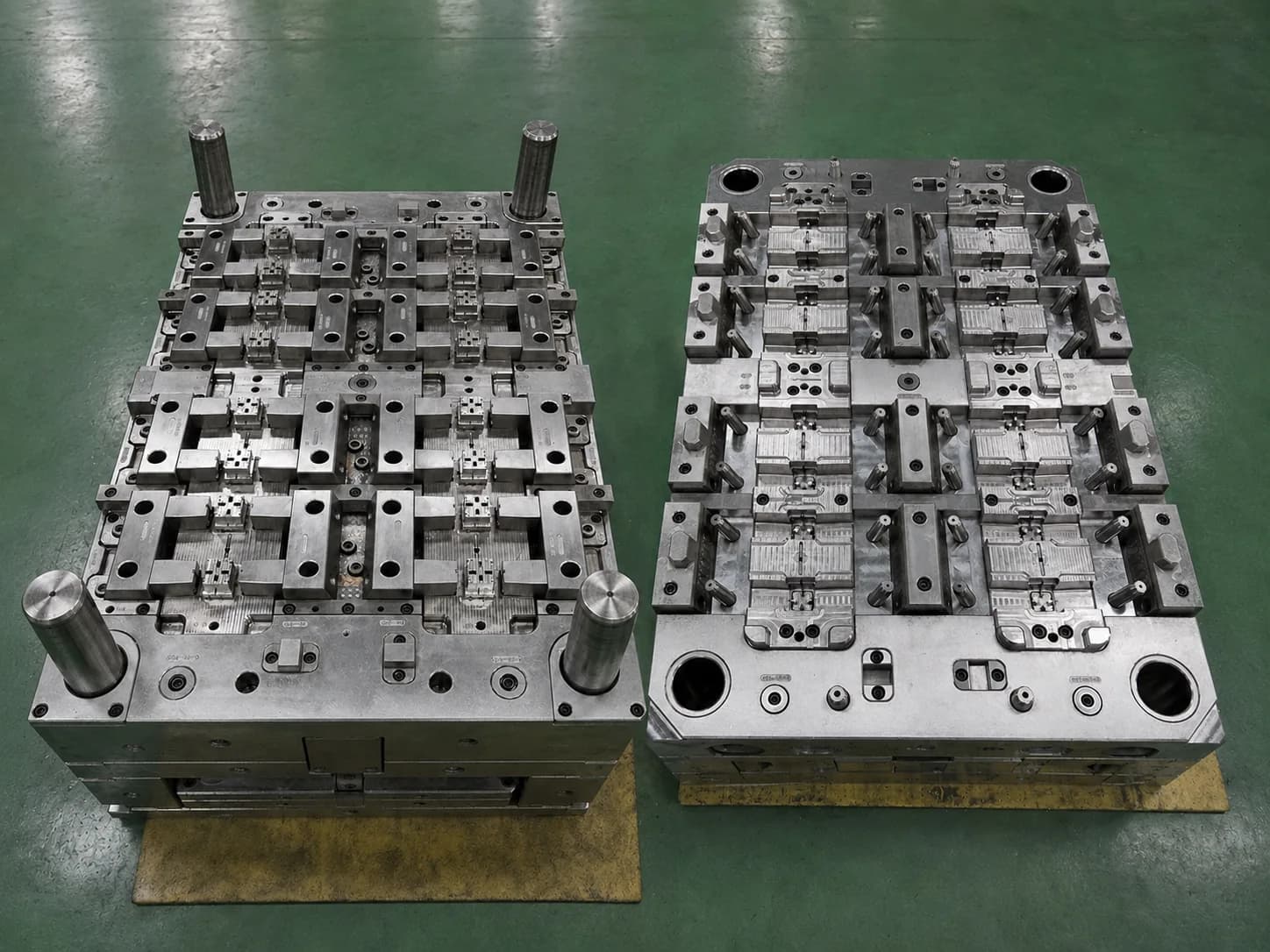
Real Multi-Cavity Tooling
This real Arktech tooling image shows open cavity and core halves with repeated production cavities, visible inserts and serviceable mold structure.
Production Value
Multiple identical parts can be produced in each molding cycle when cavity layout and machine conditions are suitable.
Higher output per cycle can reduce machine-time contribution per molded part when production volume justifies the tooling investment.
Balanced tooling can support more consistent recurring production across multiple cavities.
Cavity identification, replaceable inserts and spare tooling components can simplify maintenance planning for long-term production.
Typical Applications
Repeated small parts where stable release and cavity identification support production control.
Functional connector parts requiring repeatable interfaces across each cavity.
Compact housings and covers produced in repeat cycles for electronic assemblies.
Molded housings and functional parts reviewed against project-specific product requirements.
Enclosures, sensor housings and repeated components for connected products.
Production parts with critical fit, assembly or functional interfaces.
DFM for Multi-Cavity Tooling
Multi-cavity tooling should be evaluated as a complete molding system rather than simply duplicating a single cavity.
Balanced cold runner · Hot runner · Valve gate where required
Cavity numbering · Replaceable inserts · Spare inserts
Balanced cooling circuits · Cavity-specific venting review
Consistent ejector layout · Release behavior · Witness-mark planning
Mold size · Machine compatibility · Utility connections
Material behavior affects flow balance, shrinkage, gate wear, mold temperature and dimensional consistency across cavities.
ABS · PC · PC/ABS · PP · PA · POM · PBT
TPU / TPE where project-appropriate
Filled grades and higher-performance resins where verified
Multi-Cavity Validation
Multi-cavity validation should identify samples by cavity so filling, dimensions and correction actions can be traced to the specific cavity condition.
Review how each cavity fills, packs and responds under the selected molding conditions.
Compare appearance, gate condition, flash, burn and release marks by identified cavity.
Record critical measurements against the corresponding cavity rather than combining samples.
Trace improvement actions to the affected cavity and validate the result in a follow-up trial when required.
Documentation
Depending on project requirements, the tooling handover package can include the records needed to review trial status, cavity-specific results and ongoing maintenance.
Why Arktech for Multi-Cavity Tooling
Review cavity layout, runner strategy, cooling, release and critical dimensions before mold design approval.
Identify samples by cavity so observations and correction actions remain traceable.
Prepare agreed design, trial, inspection and handover records for the receiving production team.
Connect mold engineering with trial and molded-part production support where the project requires it.
Repeated housings, sensor parts and functional automation components.
Diagnostic housings and functional plastic components reviewed to project requirements.
Clips, connectors, controls and repeated functional components.
Sensor housings, hubs and connected-device enclosures.
Electronic enclosures and repeatable internal structural parts.
Housings, control parts and repeated functional components.
A multi-cavity injection mold contains multiple cavities for producing more than one identical part in each molding cycle. The complete layout must be engineered so filling, cooling, venting, packing, ejection and dimensional review remain controlled across the cavities.
There is no universal cavity count. The appropriate number depends on part size, material, runner layout, machine capacity, production volume, mold footprint and tooling requirements. These factors should be reviewed together during DFM and mold concept planning.
A multi-cavity mold produces multiple identical parts, while a family mold produces different related parts. Family tooling must balance unequal part volumes, geometry and demand; multi-cavity tooling focuses on consistency between repeated cavities.
Filling balance is addressed through cavity layout, runner and gate strategy, flow-length review, pressure-loss evaluation, venting and process validation. Mold flow analysis may be used when project complexity requires deeper filling analysis.
Yes, a hot runner may be considered when it fits the part geometry, resin, gate requirements, production plan and maintenance approach. A balanced cold runner can also be appropriate; the decision is project-specific.
Trial samples should be identified by cavity so visual condition, filling behavior and critical dimensions can be reviewed separately. Any correction and re-trial actions can then be traced to the affected cavity condition.
The move is considered when the product design and material are sufficiently stable, forecast demand supports the tooling investment, and cavity layout, machine capacity and quality requirements can be validated as one production system.
Start a Tooling Review
Send your CAD files, drawings, resin information, expected production volume and receiving-machine requirements for engineering review.