Undercut Mapping
Identify each undercut and assign the simplest reliable release method before mold design release.
Injection Mold Type
Complex tooling coordinates parting lines, side actions, lifters, shutoffs and ejection so parts with undercuts or difficult release geometry can be molded without damaging critical features.
What Makes This Tooling Different
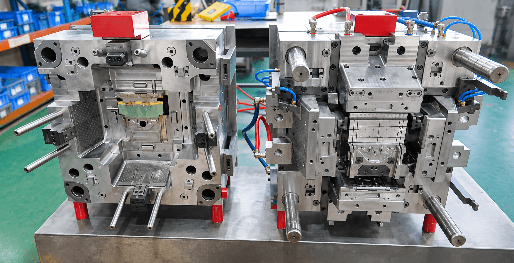
Complex molds add interacting mechanisms and release sequences that must remain protected throughout every cycle. The tooling concept must resolve how the mold opens, which action moves first, how shutoffs seal and how the part leaves the tool.
This tooling route should be selected from the part, material, production demand and receiving-machine requirements—not from a category name alone.
Selection Criteria
Parts with multiple undercuts or non-linear release
Geometry requiring coordinated slides, lifters or side actions
Complex parting lines and flash-sensitive shutoffs
Type-Specific Engineering
Identify each undercut and assign the simplest reliable release method before mold design release.
Define movement order and protection for slides, lifters, cores and ejection.
Review sealing angle, steel strength and wear at intersecting parting surfaces.
Control deformation, drag and witness marks as the part clears multiple actions.
Critical Tooling Topic
The mold movement sequence should be understandable, serviceable and protected against incorrect return positions.
Slide and lifter travel
Positive return and sequence protection
Wear inserts at shutoff areas
Ejection after all actions clear
Real Engineering Evidence
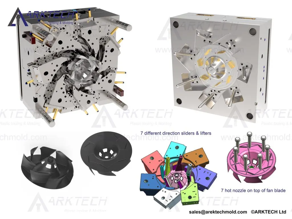
The project visual shows a real multi-action mold with visible tooling mechanisms used to release a complex molded component.
Trial & Validation
Verify every action moves and returns without interference before molding.
Review drag, deformation and witness marks around released undercuts.
Inspect complex split lines and sealing surfaces under trial pressure.
Check molded geometry and functional fit after the complete action sequence.
Related Capabilities
Project Inputs
FAQ
A complex mold is considered when part geometry cannot release through a simple two-plate opening and requires multiple side actions, lifters, cores or coordinated shutoffs.
The mold design defines travel, return position and action sequence. Mechanical protection, sensors or other safeguards may be evaluated when the tool and receiving machine require them.
They generally include more moving and wear-sensitive components. Service access, lubrication, replaceable inserts and spare-part planning therefore need earlier attention.
Validation includes dry-run movement, mold trials, release review, flash inspection, critical dimensions and confirmation of agreed correction actions.
Start Your Tooling Review
Send your CAD data, material, volume and receiving-machine requirements for DFM review and tooling quotation.