
Nozzle Layout
Coordinate nozzle positions with cavity layout, steel strength and cooling.
Injection Mold Type
Hot runner tooling keeps resin in the feed system molten between cycles and requires coordinated nozzle, gate, temperature-control and maintenance planning for the selected resin and production program.
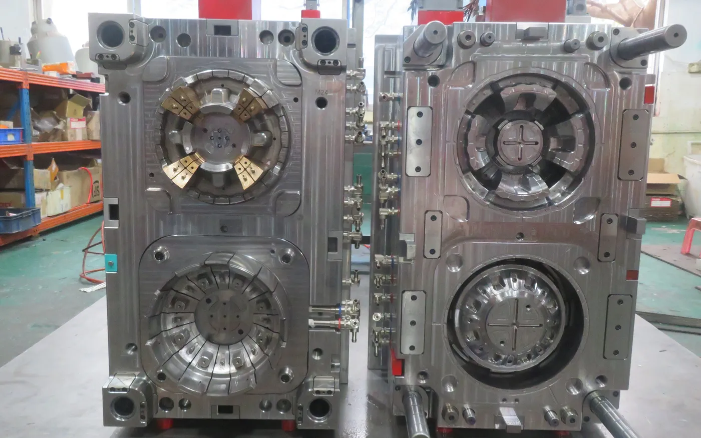
What Makes This Tooling Different
The manifold and nozzle system become part of the mold's thermal and electrical architecture. Gate quality, residence time, heat balance, controller interface and service access must be considered together.
This tooling route should be selected from the part, material, production demand and receiving-machine requirements—not from a category name alone.
Selection Criteria
Production programs where runner waste or gate control matters
Cavity layouts suited to a verified manifold concept
Receiving plants able to operate and maintain the selected system
Type-Specific Engineering
Coordinate nozzle positions with cavity layout, steel strength and cooling.
Control manifold and nozzle temperatures while limiting heat transfer into surrounding steel.
Review vestige, shear and valve-gate needs where applicable.
Plan zones, connectors, controller compatibility and service access.
Critical Tooling Topic
System selection should follow resin, cavity layout, production demand and the receiving plant's maintenance capability—not brand preference alone.
Resin and residence-time sensitivity
Open gate or valve gate where applicable
Temperature zones and connections
Nozzle and manifold service access
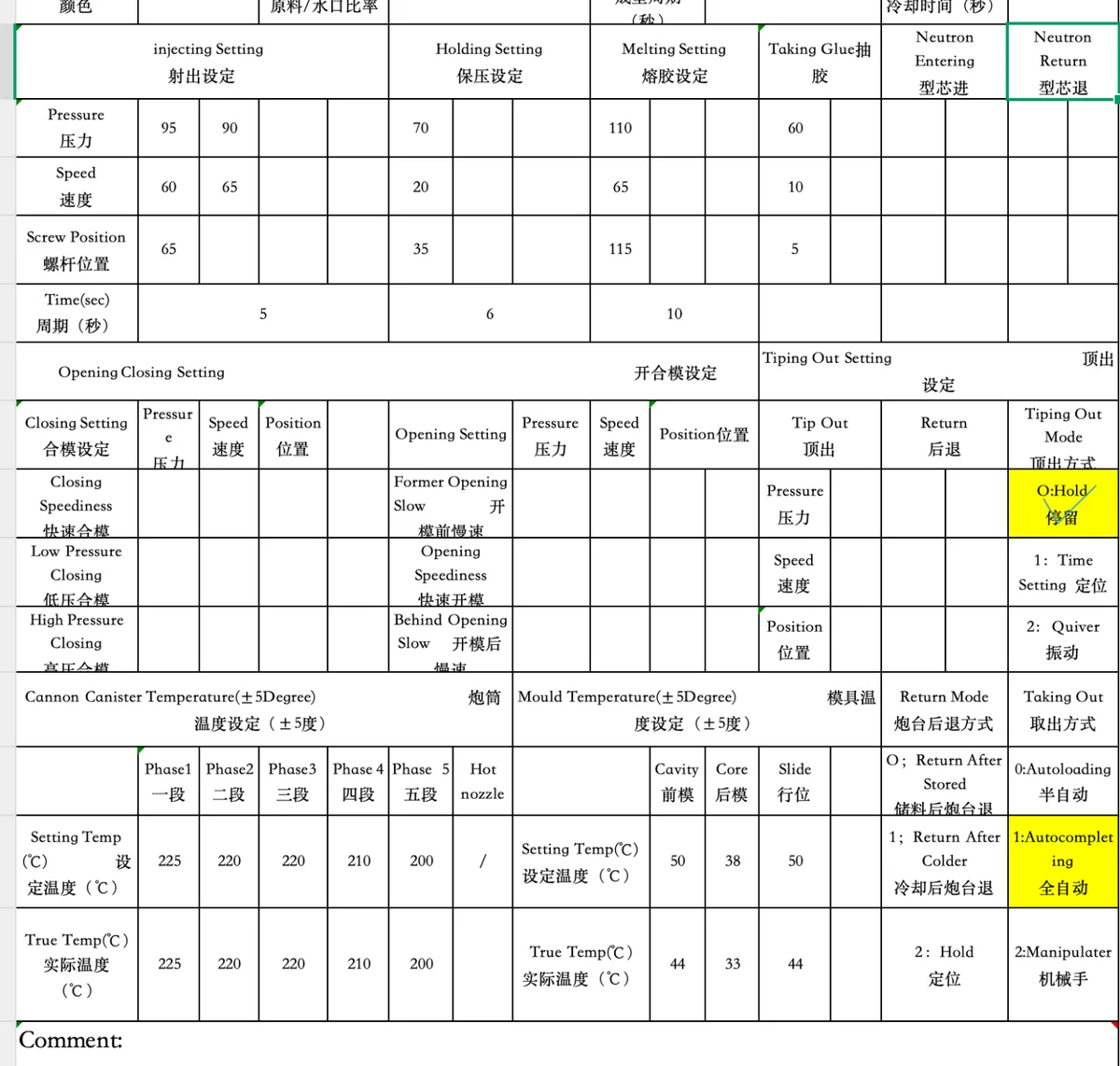
Real Engineering Evidence
The support visual is a real process-parameter record used as validation context; it does not disclose fabricated hot-runner performance data.
Trial & Validation
Review cavity filling and gate condition under stable process settings.
Record hot-runner zones and investigate abnormal heat behavior.
Inspect stringing, drool, blush or gate marks as applicable.
Verify heaters, thermocouples, connectors and agreed controller interface.
Related Capabilities
Project Inputs
FAQ
It may be considered when resin, cavity layout, runner waste, gate requirements, production demand and maintenance capability justify the added system complexity.
Valve gates may be evaluated where cavity layout, appearance, filling control and the selected system support them; they are not required for every hot-runner mold.
Controller compatibility, electrical connectors, machine interface, resin handling and maintenance expectations should be confirmed before release.
Trial review covers zone stability, filling balance, gate condition, molded appearance, process parameters and the agreed electrical and connection checks.
Start Your Tooling Review
Send your CAD data, material, volume and receiving-machine requirements for DFM review and tooling quotation.