Mold Rigidity
Support large cavity areas against pressure, deflection and long-term wear.
Injection Mold Type
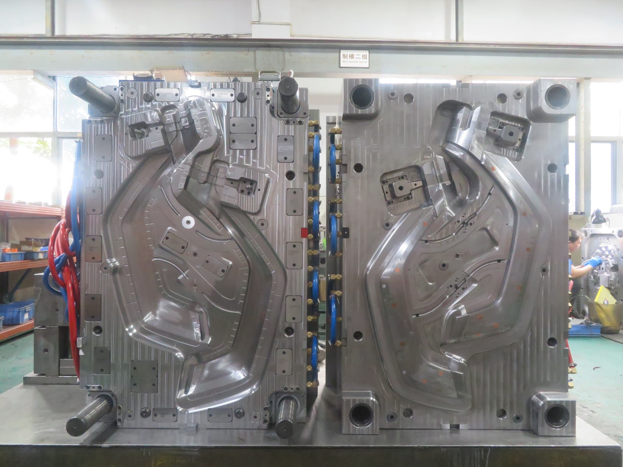
Large injection tooling is engineered around mold rigidity, cooling coverage, part shrinkage, handling and the machine interface required to produce stable housings and structural components.
What Makes This Tooling Different
As mold and part size increase, cooling uniformity, steel support, injection pressure, ejection force and safe handling become system-level decisions. A large mold must fit the receiving machine and utilities as well as the product geometry.
This tooling route should be selected from the part, material, production demand and receiving-machine requirements—not from a category name alone.
Selection Criteria
Large housings, covers or structural plastic components
Parts with broad flatness or appearance requirements
Programs with confirmed machine, crane and handling constraints
Type-Specific Engineering
Support large cavity areas against pressure, deflection and long-term wear.
Plan temperature control across broad surfaces and deep geometry.
Confirm mold envelope, tie-bar spacing, shot capacity, clamp force and utility interfaces.
Distribute release force to reduce whitening, distortion and handling damage.
Critical Tooling Topic
Large surfaces amplify uneven shrinkage and handling stress, so geometry, cooling, ejection and post-mold support must be reviewed together.
Flatness and assembly datums
Cooling circuit coverage
Balanced ejection
Lifting and transport provisions
Real Engineering Evidence
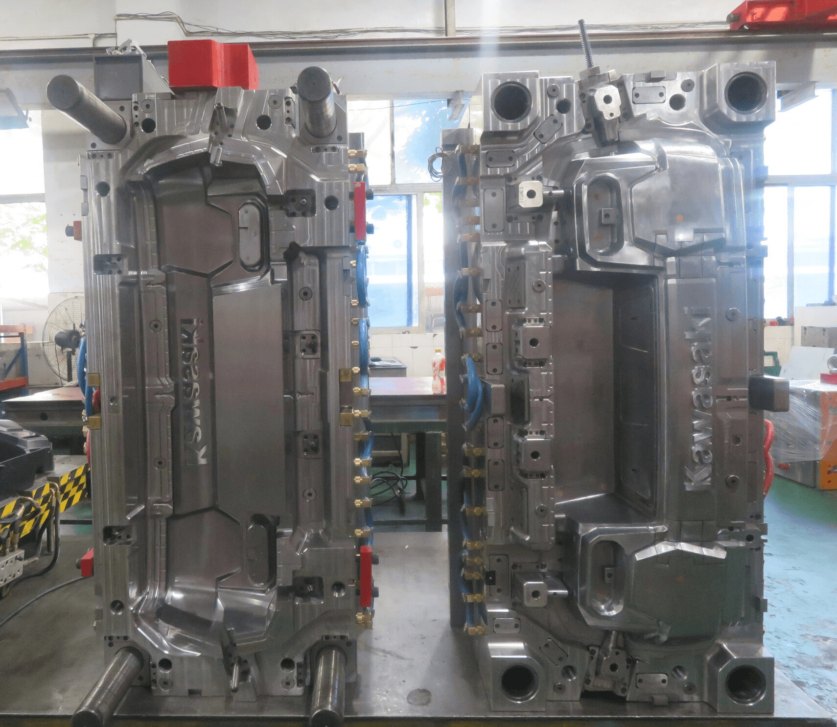
The supporting photo shows a real large mold during structural and component inspection before trial.
Trial & Validation
Measure agreed surfaces after the defined conditioning period.
Review flow, gloss, sink and gate effects across large visible zones.
Check fastening, sealing and mating interfaces on the full-size part.
Record conditions on equipment suitable for the mold and shot requirement.
Related Capabilities
Project Inputs
FAQ
CAD data, resin, part weight, annual volume, receiving-machine details, appearance requirements, critical dimensions and mold-handling standards help define the tooling concept.
DFM, wall design, gating, cooling, ejection and molding conditions are reviewed together. Final acceptance should use agreed flatness and assembly criteria.
The mold must match platen and tie-bar space, injection capacity, clamp requirements, utility connections and handling limits at the destination plant.
The agreed handover can include validation records, lifting provisions, spare parts, preservation and export packing appropriate to the receiving production environment.
Start Your Tooling Review
Send your CAD data, material, volume and receiving-machine requirements for DFM review and tooling quotation.